钝体建筑扰流的大涡模拟
-
老师们朋友们大家好,请问有没有老师或者朋友一样是做高层建筑大涡模拟风荷载的。目前遇到一个问题,在运用fluent时我采用的网格边界层厚度足够小,满足y+<1,保证可以用近壁模型计算。但是这样的网格在FOAM中对应的是运行发散。排查后发现边界层网格在不设置,或者设置的非常厚的情况下运行才会满足。想请问一下各位老师是否碰见过类似的问题?
再者由于fixed value条件一般会导致脉动风压误差变大,所以想在FOAM中运用outflow出口的时候,在foam里面一设置就会出现错误。让我用potentialfoam初始化,但是该种情况下,最终的结果也会发散。有朋友清楚该种问题是什么情况吗?
谢谢大家。 -
哪个求解器?用的什么湍流模型。网格是六面体么
-
@李东岳 李老师您好,采用的是pisofoam算法,求解器p用的是GAMG,U用的是PBICG。湍流模型LES-WALE,使用的是fluentmeshing生成的多面体网格。该网格在fluent中已经运算过,得到的结果很不错。来到FOAM罢工了。个人估计是边界层的问题,模型尺寸为0.1m0.1m0.1m,整个计算域尺寸为8m4m1.6m。我的建筑面面网格的尺寸是0.002m,为了满足y+<1,建筑表面的边界层网格厚度是0.00005m。地面厚度的全局最大尺寸为0.05m,地面边界层网格的厚度是0.0005m。也曾在一篇帖子下发现您推荐的snappyHexMesh,但是生成质量不佳,有时候甚至边界层网格无法生成。目前用OpenFOAM做LES建筑风荷载的文献也没怎么查到,导致困在这了
-
log贴一下,按照这种代码的方式
log
-
@李东岳 速度出口是零梯度边界,压力出口是固定值,速度入口是固定值,压力入口是零梯度
-
@hitsc30 什么类型的建筑物?
https://link.springer.com/article/10.1007/s10546-020-00574-1
这是我之前做的,openfoam + 小方块。有什么需要可以邮件联系。tiang@sustech.edu.cn -
\*---------------------------------------------------------------------------*/ FoamFile { version 2.0; format ascii; class volVectorField; location "1"; object U; } // * * * * * * * * * * * * * * * * * * * * * * * * * * * * * * * * * * * * * // dimensions [0 1 -1 0 0 0 0]; internalField uniform (0 0 0); boundaryField { inlet { type timeVaryingMappedFixedValue; offset (0 0 0); setAverage off; } outlet { type zeroGradient; } upperwall { type symmetry; } bottom { type noSlip; } symmetry { type symmetry; } building { type noSlip; } }
// ************************************************************************* // /*--------------------------------*- C++ -*----------------------------------*\ | ========= | | | \\ / F ield | OpenFOAM: The Open Source CFD Toolbox | | \\ / O peration | Version: v2012 | | \\ / A nd | Website: www.openfoam.com | | \\/ M anipulation | | \*---------------------------------------------------------------------------*/ FoamFile { version 2.0; format ascii; class volScalarField; location "1"; object p; } // * * * * * * * * * * * * * * * * * * * * * * * * * * * * * * * * * * * * * // dimensions [0 2 -2 0 0 0 0]; internalField uniform 0; boundaryField { inlet { type zeroGradient; } outlet { type fixedValue; value uniform 0; //type zeroGradient; } upperwall { type symmetry; } bottom { type zeroGradient; } symmetry { type symmetry; } building { type zeroGradient; } }
// ************************************************************************* // /*--------------------------------*- C++ -*----------------------------------*\ | ========= | | | \\ / F ield | OpenFOAM: The Open Source CFD Toolbox | | \\ / O peration | Version: v2012 | | \\ / A nd | Website: www.openfoam.com | | \\/ M anipulation | | \*---------------------------------------------------------------------------*/ FoamFile { version 2.0; format ascii; class volScalarField; location "1"; object nut; } // * * * * * * * * * * * * * * * * * * * * * * * * * * * * * * * * * * * * * // dimensions [0 2 -1 0 0 0 0]; internalField uniform 0; boundaryField { inlet { type calculated; value uniform 0; } outlet { type calculated; value uniform 0; } upperwall { type symmetry; } bottom { type nutUSpaldingWallFunction; value $internalField; //type fixedValue; //value uniform 0; } symmetry { type symmetry; } building { type nutUSpaldingWallFunction; value $internalField; //type fixedValue; //value uniform 0; } }
// ************************************************************************* // /*--------------------------------*- C++ -*----------------------------------*\ | ========= | | | \\ / F ield | OpenFOAM: The Open Source CFD Toolbox | | \\ / O peration | Version: v2012 | | \\ / A nd | Website: www.openfoam.com | | \\/ M anipulation | | \*---------------------------------------------------------------------------*/ FoamFile { version 2.0; format ascii; class dictionary; location "constant"; object turbulenceProperties; } // * * * * * * * * * * * * * * * * * * * * * * * * * * * * * * * * * * * * * // simulationType LES; LES { LESModel WALE; turbulence on; printCoeffs on; delta cubeRootVol; cubeRootVolCoeffs { deltaCoeff 1; } PrandtlCoeffs { delta cubeRootVol; cubeRootVolCoeffs { deltaCoeff 1; } smoothCoeffs { delta cubeRootVol; cubeRootVolCoeffs { deltaCoeff 1; } maxDeltaRatio 1.1; } Cdelta 0.158; } vanDriestCoeffs { delta cubeRootVol; cubeRootVolCoeffs { deltaCoeff 1; } smoothCoeffs { delta cubeRootVol; cubeRootVolCoeffs { deltaCoeff 1; } maxDeltaRatio 1.1; } Aplus 26; Cdelta 0.158; } smoothCoeffs { delta cubeRootVol; cubeRootVolCoeffs { deltaCoeff 1; } maxDeltaRatio 1.1; } }
// ************************************************************************* // /*--------------------------------*- C++ -*----------------------------------*\ | ========= | | | \\ / F ield | OpenFOAM: The Open Source CFD Toolbox | | \\ / O peration | Version: 4.x | | \\ / A nd | Web: www.OpenFOAM.org | | \\/ M anipulation | | \*---------------------------------------------------------------------------*/ FoamFile { version 2.0; format ascii; class dictionary; location "system"; object fvSchemes; } // * * * * * * * * * * * * * * * * * * * * * * * * * * * * * * * * * * * * * // //shijianyijiedushuxiang ddtSchemes // { default backward; } //tidu gradSchemes { default Gauss linear; //grad(nuTilda) cellLimited Gauss linear 1; //grad(U) cellLimited Gauss linear 1; //grad(P) Gauss linear; } //sandduxiang divSchemes ///////////////////////////////////////////////////// { default none; div(phi,U) bounded Gauss linearUpwind grad(U); div(phi,k) bounded Gauss linearUpwind grad(k); div(phi,B) bounded Gauss linearUpwind grad(B); div(phi,omega) bounded Gauss linearUpwind grad(omega); div(phi,B) bounded Gauss linear; //div(phi,nuTilda) Gauss limitedLinear 1; div((nuEff*dev2(T(grad(U))))) Gauss linear; } laplacianSchemes // { default Gauss linear limited corrected 0.33; } interpolationSchemes // { default linear; } snGradSchemes // { default limited corrected 0.33; } wallDist { method meshWave; }
// ************************************************************************* // /*--------------------------------*- C++ -*----------------------------------*\ | ========= | | | \\ / F ield | OpenFOAM: The Open Source CFD Toolbox | | \\ / O peration | Version: 4.x | | \\ / A nd | Web: www.OpenFOAM.org | | \\/ M anipulation | | \*---------------------------------------------------------------------------*/ FoamFile { version 2.0; format ascii; class dictionary; location "system"; object fvSolution; } // * * * * * * * * * * * * * * * * * * * * * * * * * * * * * * * * * * * * * // solvers { p { solver GAMG; tolerance 1e-6; relTol 0.1; smoother GaussSeidel; //nCellsInCoarsestLevel 50; } pFinal { $p; tolerance 1e-6; relTol 0; } U { solver PBiCG; preconditioner DILU; tolerance 1e-6; relTol 0.05; } UFinal { solver PBiCG; preconditioner DILU; tolerance 1e-6; relTol 0; } } PISO { nCorrectors 3; nNonOrthogonalCorrectors 1; //pRefCell 0; pRefPoint (2 0 1.5); pRefValue 0; } relaxationFactors { fields { p 0.3; } equations { U 1; } //"U.*" 0.5; //"nuTilda.*" 1; } // ************************************************************************* //
李老师这是我的设置,感谢各位老师朋友的解答
-
@zhouxu 对的老师,对p用零梯度一直发散,potentialfoam后也存在这种情况,后面就用了固定值。不过看文献说p采用固定值会增大脉动风压的误差。
-
@gtian 谢谢!我第一个case也是规整的方形建筑物,采用的大涡模拟计算的。目前在看如何采用商软生成多面体网格,保证能有一个好的收敛结果。fluent用的网格在foam罢工了
-
snappyHexMeshDict 中把snap 和 add 关掉,就会生成结构化的六面体网格,网格质量会号很多, 只需要有stl文件即可.
// Which of the steps to run castellatedMesh true; snap false; addLayers false; geometry { flange11.stl { type triSurfaceMesh; name flange11; }
stl文件如下:
solid flange facet normal 0 0 -1 outer loop vertex 0.170 0.000 0.230 vertex 0.170 0.020 0.230 vertex 0.190 0.020 0.230 endloop endfacet facet normal 0 0 -1 outer loop vertex 0.170 0.000 0.230 vertex 0.190 0.020 0.230 vertex 0.190 0.000 0.230 endloop endfacet facet normal -1 0 0 outer loop vertex 0.170 0.000 0.230 vertex 0.170 0.000 0.210 vertex 0.170 0.020 0.210 endloop endfacet facet normal -1 0 0 outer loop vertex 0.170 0.000 0.230 vertex 0.170 0.020 0.210 vertex 0.170 0.020 0.230 endloop endfacet facet normal 0 -1 0 outer loop vertex 0.170 0.000 0.230 vertex 0.190 0.000 0.210 vertex 0.190 0.000 0.230 endloop endfacet facet normal 0 -1 0 outer loop vertex 0.170 0.000 0.230 vertex 0.190 0.000 0.210 vertex 0.170 0.000 0.210 endloop endfacet facet normal 0 0 1 outer loop vertex 0.170 0.000 0.210 vertex 0.190 0.000 0.210 vertex 0.190 0.020 0.210 endloop endfacet facet normal 0 0 1 outer loop vertex 0.170 0.000 0.210 vertex 0.190 0.020 0.210 vertex 0.170 0.020 0.210 endloop endfacet facet normal 1 0 0 outer loop vertex 0.190 0.000 0.230 vertex 0.190 0.020 0.230 vertex 0.190 0.020 0.210 endloop endfacet facet normal 1 0 0 outer loop vertex 0.190 0.000 0.230 vertex 0.190 0.020 0.210 vertex 0.190 0.000 0.210 endloop endfacet facet normal 0 1 0 outer loop vertex 0.170 0.020 0.230 vertex 0.170 0.020 0.210 vertex 0.190 0.020 0.210 endloop endfacet facet normal 0 1 0 outer loop vertex 0.170 0.020 0.230 vertex 0.190 0.020 0.230 vertex 0.190 0.020 0.210 endloop endfacet endsolid flange
-
@gtian 感谢回复。我模拟的是建筑风压,感觉将边界层去掉的情况下,有点难搞
非常感谢您的帮助 -
@hitsc30 如果你提到的边界层指的是wall周围的对数区以下的粘性子层和buffer layer的话。可以有两种方式,一种是wall model LES,通过壁面模型来调nut,这时第一层网格在y+=30 即可。另一种是wall resolved LES,这种情况只能加密网格。blockmesh和shm都可以加密网格,blockmesh可以控制aspect ratio来加密,shm是4等分加密。这种情况下如果要resolve到粘性子层(viscous sublayer),需要在y+<5 以内至少有三个点,也就是第一点y+<1.
-
@hitsc30 你这个涉及的东西有点多,排查起来会比较复杂。首先建议抛开fluent里的设置,因为大涡模拟这块openfoam和fluent差的还有点多。
首先是网格,snappy如果不好生成的话,试试cfmesh,这个比snappy好用,比fluentmeshing我感觉也就是边界层生成差一些。考虑到你这个几何相对应该比较规整,cfmesh应该可以的。
其次是入口条件。openfoam大涡模拟的入口条件这块是不如fluent的vortex method的,fluent的很好用,不怎么发散,生成的湍流也很强。我看你用的是timeVaryingMappedFixedValue,这是用的实验数据或者测试数据吗?你fluent是怎么用的?
然后是nut的边界条件,我之前也是发现nutUSpaldingWallFunction很好用,但我不确定它应该和WALE一起。WALE一般是传热领域用的多,原因是这个模型是不需要壁面函数的,而传热主要就是要解析壁面,不能模化。WALE感觉和你加的nut边界条件可能会冲突?
再然后是数值格式,一个是pisoFoam,openfoam里面的pisoFoam外迭代只有一步,可能收敛不太好。试试pimpleFoam加上外迭代吧,这个其实你在fluent里面应该也设置过。或者把你目前计算的残差曲线贴出来看看。
最后,为了排查这些问题,建议先跑个非稳态的RANS试试,不然理不出头绪来。其实最好先跑个稳态RANS,没问题了再非稳态RANS,再没问题了再上LES。
-
@gtian 在 钝体建筑扰流的大涡模拟 中说:
@hitsc30 如果你提到的边界层指的是wall周围的对数区以下的粘性子层和buffer layer的话。可以有两种方式,一种是wall model LES,通过壁面模型来调nut,这时第一层网格在y+=30 即可。另一种是wall resolved LES,这种情况只能加密网格。blockmesh和shm都可以加密网格,blockmesh可以控制aspect ratio来加密,shm是4等分加密。这种情况下如果要resolve到粘性子层(viscous sublayer),需要在y+<5 以内至少有三个点,也就是第一点y+<1.
感谢回复,这个确实可以在后续重点突击一下。此前我曾用blockmesh做网格背景、snappyhexmesh加密做过一个网格。当时我得到的计算值也和我用fluentmeshing商软所做的商业网格差不太多,没太考虑网格的质量。您提出的这个是我当前需要考虑的一个方向。我当前觉得目前比较影响我接过的可能是离散格式,在这方面的知识储备非常的欠缺,只能选一些高阶离散格式,可能对结果有不小的影响。 -
@cccrrryyy 您好,感谢回复。目前接触到的在openfoam中做建筑风荷载模拟的论文主要是tamura教授在北京交通大学和重庆大学领导的学科组推出来的,都采用的是pisofoam算法。湍流风入口是由CDRFG方法生成的,在中文网有个帖子谈论过这种植入。也咨询过北交的师兄,他们植入的CDRFG算法也是类似的植入,该方法应该是没有问题的。
nut函数,我也和您的观点一样。该函数能自动切换成粘性层的线性表达式和对数表达式。再者是您提出的WALE,这个确实是需要改动一下.目前接触的论文中,foam中都是用的经典的smagorinksy。fluent中,国内硕士很多用的是WALE结果对的确实不是很好。您提到的WALE这个模型的具体作用,对代码认识比较浅,确实之前没考虑过,确实是我需要再次调整的方向。
当前的两个重点是离散格式和亚格子模型,然后是上面的师兄说的网格的质量。
ps:感觉foam计算y+很奇怪,我的边界层网格每次改变的不少,感觉y+变化趋势和我想的南辕北辙。 -
你可以把你的网格截图一下 看看能差到什么样子
-
@hitsc30
y+ 的理解不复杂,看code需要一点点的耐心就可以。我给你贴一下yPlusLES。if (isA<wallFvPatch>(currPatch)) { yPlus.boundaryField()[patchi] = d[patchi] *sqrt ( nuEff.boundaryField()[patchi] *mag(U.boundaryField()[patchi].snGrad()) ) /nuLam.boundaryField()[patchi]; const scalarField& Yp = yPlus.boundaryField()[patchi]; Info<< "Patch " << patchi << " named " << currPatch.name() << " y+ : min: " << gMin(Yp) << " max: " << gMax(Yp) << " average: " << gAverage(Yp) << nl << endl; }


我写的,你可以输出来看看每一个量的大小
if (isA<wallFvPatch>(currPatch)) { frictionvelocityLES.boundaryField()[patchi] = sqrt ( nuEff.boundaryField()[patchi] *mag(U.boundaryField()[patchi].snGrad()) ); const scalarField& Yp = frictionvelocityLES.boundaryField()[patchi]; Info<< "Patch " << patchi << " named " << currPatch.name() << " friction velocity u* : min: " << gMin(Yp) << " max: " << gMax(Yp) << " average: " << gAverage(Yp) << nl << endl; Info<< "Patch " << patchi << " named " << currPatch.name() << "nuLam : min: " << gMin(nuLam) << " max: " << gMax(nuLam) << " average: " << gAverage(nuLam) << nl << endl; Info<< "Patch " << patchi << " named " << currPatch.name() << "d : min: " << gMin(d) << " max: " << gMax(d) << " average: " << gAverage(d) << nl << endl; }
近壁面第一层网格的话 ,d= 0.5* 第一个cell的长度. du/dy = (u_infty - 0)/ (d-0)
nuefff = nu (层流 laminar) + nut(wall 上 nut =0 或者是你给的壁面模型的值)我给的nut在壁面上就是0.
object nuSgs; } // * * * * * * * * * * * * * * * * * * * * * * * * * * * * * * * * * * * * * // dimensions [ 0 2 -1 0 0 0 0 ]; internalField uniform 0; boundaryField { bottomWall { type fixedValue; value uniform 0; }
-
@gtian 在 钝体建筑扰流的大涡模拟 中说:
@hitsc30
y+ 的理解不复杂,看code需要一点点的耐心就可以。我给你贴一下yPlusLES。if (isA<wallFvPatch>(currPatch)) { yPlus.boundaryField()[patchi] = d[patchi] *sqrt ( nuEff.boundaryField()[patchi] *mag(U.boundaryField()[patchi].snGrad()) ) /nuLam.boundaryField()[patchi]; const scalarField& Yp = yPlus.boundaryField()[patchi]; Info<< "Patch " << patchi << " named " << currPatch.name() << " y+ : min: " << gMin(Yp) << " max: " << gMax(Yp) << " average: " << gAverage(Yp) << nl << endl; }


我写的,你可以输出来看看每一个量的大小
if (isA<wallFvPatch>(currPatch)) { frictionvelocityLES.boundaryField()[patchi] = sqrt ( nuEff.boundaryField()[patchi] *mag(U.boundaryField()[patchi].snGrad()) ); const scalarField& Yp = frictionvelocityLES.boundaryField()[patchi]; Info<< "Patch " << patchi << " named " << currPatch.name() << " friction velocity u* : min: " << gMin(Yp) << " max: " << gMax(Yp) << " average: " << gAverage(Yp) << nl << endl; Info<< "Patch " << patchi << " named " << currPatch.name() << "nuLam : min: " << gMin(nuLam) << " max: " << gMax(nuLam) << " average: " << gAverage(nuLam) << nl << endl; Info<< "Patch " << patchi << " named " << currPatch.name() << "d : min: " << gMin(d) << " max: " << gMax(d) << " average: " << gAverage(d) << nl << endl; }
近壁面第一层网格的话 ,d= 0.5* 第一个cell的长度. du/dy = (u_infty - 0)/ (d-0)
nuefff = nu (层流 laminar) + nut(wall 上 nut =0 或者是你给的壁面模型的值)我给的nut在壁面上就是0.
object nuSgs; } // * * * * * * * * * * * * * * * * * * * * * * * * * * * * * * * * * * * * * // dimensions [ 0 2 -1 0 0 0 0 ]; internalField uniform 0; boundaryField { bottomWall { type fixedValue; value uniform 0; }
非常感谢!
-
@李东岳
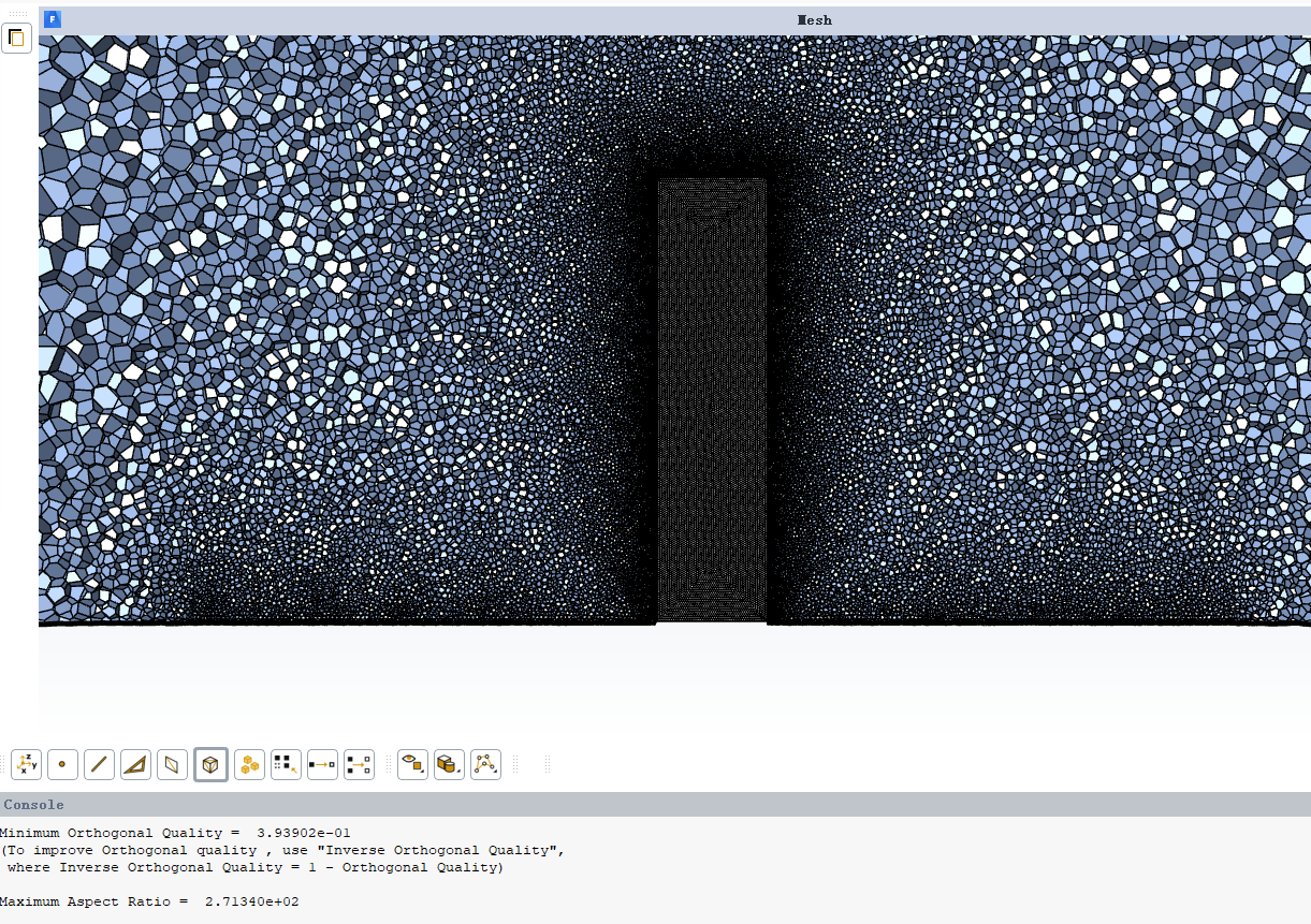
抱歉,李博。这几天电脑卡的要死,开启fluentmeshing就卡死,一直想着要回复您。但是也没法打开软件。这是我再fluentmeshing中检测的问题。我当前的问题主要是,我画过粗略的多面体和精细的多面体网格是否对于结果优化都没太大的影响了。当前想着试一试snappyhexmesh画六面体拯救一下我,在使用中发现其对于边界层网格生成有点随缘化,网格在90度拐角处处理的不是很好。
-
@hitsc30 你这个网格用openfoam跑没问题啊,为啥要用snappyHexMesh呢。你是说网格粗细对结果没啥影响?这是有可能的。你可以发线图看一下对比一下结果
-
@李东岳 李老师我上点图给您和各位老师看一下。我们使用了fluent和openfoam进行平均风剖面的模拟。下图是我们得到的结果
下述是平均风剖面对比:
而后是我用脉动算出来的结果,分别是平均风压和脉动风压
下述是我的实验数据迎风面风压和模拟的迎风面风压
误差有点离谱
当前是按照tamura教授的设置帮边界条件、离散格式、求解器、亚格子模型全换了。就是采用的网格和他们的有所区别(他们采用的snappyhexmesh),准备搞个和他们一样的网格试一试。实在不行就只能放弃了
主要现在用foam用了半年,从一个啥都不知道的小白在师兄和论坛的各位前辈带着下,慢慢的进步对这个东西用习惯了,人菜瘾大。就想证实到底是我设置什么的不行,还是foam可能这方面存在改进。就是最后放弃foam改用fluent算也不让自己后悔。 -
@李东岳 目前就是除了网格和他们有所不同之外,我期望的那个数值再也上不去了。现在就是打算试试那几篇论文中的网格生成方法了
-
@李东岳 这是最粗糙的网格所得结果
这是第一次改善后
这是第三次改善后
没得进步空间了 -
这个几何这么简单,为什么不上纯六面体网格呢? 另外我看你这两个图差别很小啊
-
@hitsc30
看你的离散格式,对流项 div(phi,U) 使用的是 linearUpwind,这个格式不适合用于 LES 仿真,数值耗散太大。建议尝试一下 LUST,或者 filteredLinear2 这类格式。
还有,如果用 PISO 求解器,p 不要用松弛。你现在用的是 0.3,这个是错的。
-
@李东岳 东岳老师,不上纯六面体的原因在于计算量的太大。我的工况很多,想着多面体什么的减少点计算量。涉及到课题的意义,没有办法,2/3高度处看着还行,但是迎风面整体小了0.1。有点点大
-
@xpqiu 感谢老师回复。起始选用这个格式的时候是基于下述这篇论文,当时理解错了,算了一个二姐迎风格式的。后续和在日本留学的师兄交流过。他们那边计算多采用您推荐的lust这个,后续全部改成这个了。您说的piso这个对于field中的p松弛是参考了一篇博士论文,我一直没做深究。我一会上服务器跑一个案例试一试。感谢各位老师的关心办帮助!!!明早跑出结果和各位老师朋友分享一下!
-
更新一下昨晚的结果,对于精密化的多面体网格,即保证边界层y+<1,计算发散。对于较为粗糙的网格,即保证y+大于30时,网格可以计算,但最终结果存在发散现象。我打算再试一试snappyhexmesh网格,以及把精密化网格再改正一下,看看结果如何。
-
@hitsc30 在 钝体建筑扰流的大涡模拟 中说:
当前是按照tamura教授的设置帮边界条件、离散格式、求解器、亚格子模型全换了。就是采用的网格和他们的有所区别(他们采用的snappyhexmesh),准备搞个和他们一样的网格试一试。实在不行就只能放弃了
方便把建筑物的详细参数,以及对标的那篇实验分享一下吗?我跑一下看看。压力系数就是一个静压,如果这个都对不上,高阶统计量就能不可能了,那LES的作用就被完完全全浪费。 就算一个建筑物的话,这个已经属于10多年的范畴了,2006年就能跑DNS了。
https://www.sciencedirect.com/science/article/pii/S0142727X06000476 -
@gtian 您好,我研究的对象是基于东京工艺大学TPU数据库的1:1:4模型的模拟(在和风洞同样缩尺1:400后,模型的尺寸为0.1m0.1m0.4m。α为0.25,计算域按照cost732推荐为长8m宽4m高度为1.6m)。TPU数据库参见下述链接:
http://www.wind.arch.t-kougei.ac.jp/system/eng/contents/code/w_it
对标的就是该风压数据库提供数据处理得到的平均风压系数和脉动风压系数。当前我的平均风压系数一直偏小了0.1; -
@hitsc30 在 钝体建筑扰流的大涡模拟 中说:
@gtian 您好,我研究的对象是基于东京工艺大学TPU数据库的1:1:4模型的模拟(在和风洞同样缩尺1:400后,模型的尺寸为0.1m0.1m0.4m。α为0.25,计算域按照cost732推荐为长8m宽4m高度为1.6m)。TPU数据库参见下述链接:
http://www.wind.arch.t-kougei.ac.jp/system/eng/contents/code/w_it
对标的就是该风压数据库提供数据处理得到的平均风压系数和脉动风压系数。当前我的平均风压系数一直偏小了0.1;迎风向缩尺后尺寸为0.1m,顺风向缩尺后尺寸为0.1m,竖向的尺寸为0.4m。指数选取为0.25
-
@hitsc30 雷诺数大概是多少呢?这个实验有发过什么文章吗?压力系数只是迎风面上的吗?
-
@gtian 有一篇类似的文章,该文章研究的模型是1:1:5模型。我研究的是1:1:4模型,在TPU数据库上实际有四百个个测点,每个面各有一百个测点。
下述链接是1:1:5模型的文件,链接如下,国内有人做过1:1:4模型,基于fluent平台进行的模拟,结果还未见刊。
https://www.sciencedirect.com/science/article/pii/S0167610520303202
雷诺数,在建筑高度处大约30w。计算高度处模型高度0.4m(对应实际高度160m),风速11m/s。风洞数据库参见链接:
http://www.wind.arch.t-kougei.ac.jp/system/eng/contents/code/w_it
祝大家五四青年节快乐! -
更新一下,跑了几天。
- 两个时间尺度,
timestep \delta T , 控制Co < 2.
总运行时长: 第一阶段250个大涡turnover time : 250 * (0.4(H) / 0.5 (friction velocity); 第二阶段100个大涡turnover time .
2.
4. Mesh stats points: 3520103 faces: 10396800 internal faces: 10234752 cells: 3438592 faces per cell: 6 boundary patches: 23 point zones: 0 face zones: 0 cell zones: 0 Overall number of cells of each type: hexahedra: 3438592 prisms: 0 wedges: 0 pyramids: 0 tet wedges: 0 tetrahedra: 0 polyhedra: 0 Checking topology... Boundary definition OK. Cell to face addressing OK. Point usage OK. Upper triangular ordering OK. Face vertices OK. Number of regions: 1 (OK). Checking patch topology for multiply connected surfaces... Patch Faces Points Surface topology bottomWall 49088 49552 ok (non-closed singly connected) topWall 49152 49601 ok (non-closed singly connected) sides1_half0 12288 12593 ok (non-closed singly connected) sides1_half1 12288 12593 ok (non-closed singly connected) sides2_half0 3072 3341 ok (non-closed singly connected) sides2_half1 3072 3341 ok (non-closed singly connected) sides3_half0 1536 1799 ok (non-closed singly connected) sides3_half1 1536 1799 ok (non-closed singly connected) sides4_half0 768 1028 ok (non-closed singly connected) sides4_half1 768 1028 ok (non-closed singly connected) sides5_half0 256 514 ok (non-closed singly connected) sides5_half1 256 514 ok (non-closed singly connected) out1_half0 9216 9457 ok (non-closed singly connected) in1_half1 9216 9457 ok (non-closed singly connected) out2_half0 2304 2509 ok (non-closed singly connected) in2_half1 2304 2509 ok (non-closed singly connected) out3_half0 1152 1351 ok (non-closed singly connected) in3_half1 1152 1351 ok (non-closed singly connected) out4_half0 576 772 ok (non-closed singly connected) in4_half1 576 772 ok (non-closed singly connected) out5_half0 192 386 ok (non-closed singly connected) in5_half1 192 386 ok (non-closed singly connected) building 1088 1105 ok (non-closed singly connected) Checking geometry... Overall domain bounding box (0 0 0) (3.2 1.6 2.4) Mesh (non-empty, non-wedge) directions (1 1 1) Mesh (non-empty) directions (1 1 1) Boundary openness (8.71455e-17 -4.51544e-16 -4.1172e-16) OK. Max cell openness = 1.73472e-16 OK. Max aspect ratio = 12.6864 OK. Minimum face area = 0.00015625. Maximum face area = 0.00198225. Face area magnitudes OK. Min volume = 1.95312e-06. Max volume = 2.47781e-05. Total volume = 12.284. Cell volumes OK. Mesh non-orthogonality Max: 0 average: 0 Non-orthogonality check OK. Face pyramids OK. Max skewness = 3.18096e-13 OK. Coupled point location match (average 0) OK. Mesh OK. End
- 两个时间尺度,
-
/*--------------------------------*- C++ -*----------------------------------*\ | ========= | | | \\ / F ield | OpenFOAM: The Open Source CFD Toolbox | | \\ / O peration | Version: 2.4.0 | | \\ / A nd | Web: www.OpenFOAM.org | | \\/ M anipulation | | \*---------------------------------------------------------------------------*/ FoamFile { version 2.0; format ascii; class volScalarField; location "0"; object p; } // * * * * * * * * * * * * * * * * * * * * * * * * * * * * * * * * * * * * * // dimensions [ 0 2 -2 0 0 0 0 ]; internalField uniform 0; boundaryField { bottomWall { type zeroGradient; } topWall { type symmetryPlane; } sides1_half0 { type symmetryPlane; } sides2_half0 { type symmetryPlane; } sides3_half0 { type symmetryPlane; } sides4_half0 { type symmetryPlane; } sides5_half0 { type symmetryPlane; } out1_half0 { type fixedValue; value uniform 0; } out2_half0 { type fixedValue; value uniform 0; } out3_half0 { type fixedValue; value uniform 0; } out4_half0 { type fixedValue; value uniform 0; } out5_half0 { type fixedValue; value uniform 0; } sides5_half1 { type symmetryPlane; } sides4_half1 { type symmetryPlane; } sides3_half1 { type symmetryPlane; } sides2_half1 { type symmetryPlane; } sides1_half1 { type symmetryPlane; } in1_half1 { type zeroGradient; } in2_half1 { type zeroGradient; } in3_half1 { type zeroGradient; } in4_half1 { type zeroGradient; } in5_half1 { type zeroGradient; } building { type zeroGradient; } } // ************************************************************************* //
/*--------------------------------*- C++ -*----------------------------------*\ | ========= | | | \\ / F ield | OpenFOAM: The Open Source CFD Toolbox | | \\ / O peration | Version: 2.4.0 | | \\ / A nd | Web: www.OpenFOAM.org | | \\/ M anipulation | | \*---------------------------------------------------------------------------*/ FoamFile { version 2.0; format ascii; class volVectorField; location "0"; object U; } // * * * * * * * * * * * * * * * * * * * * * * * * * * * * * * * * * * * * * // dimensions [ 0 1 -1 0 0 0 0 ]; internalField uniform ( 0.01335 0 0 ); boundaryField { bottomWall { type fixedValue; value uniform ( 0 0 0 ); } topWall { type symmetryPlane; } sides1_half0 { type symmetryPlane; } sides2_half0 { type symmetryPlane; } sides3_half0 { type symmetryPlane; } sides4_half0 { type symmetryPlane; } sides5_half0 { type symmetryPlane; } out1_half0 { type inletOutlet; inletValue uniform (0 0 0); value uniform (0 0 0); } out2_half0 { type inletOutlet; inletValue uniform (0 0 0); value uniform (0 0 0); } out3_half0 { type inletOutlet; inletValue uniform (0 0 0); value uniform (0 0 0); } out4_half0 { type inletOutlet; inletValue uniform (0 0 0); value uniform (0 0 0); } out5_half0 { type inletOutlet; inletValue uniform (0 0 0); value uniform (0 0 0); } sides5_half1 { type symmetryPlane; } sides4_half1 { type symmetryPlane; } sides3_half1 { type symmetryPlane; } sides2_half1 { type symmetryPlane; } sides1_half1 { type symmetryPlane; } in1_half1 { type turbulentInlet; referenceField uniform (9 0 0); fluctuationScale (0.02 0.01 0.01); value uniform (9 0 0); } in2_half1 { type turbulentInlet; referenceField uniform (9 0 0); fluctuationScale (0.02 0.01 0.01); value uniform (9 0 0); } in3_half1 { type turbulentInlet; referenceField uniform (9 0 0); fluctuationScale (0.02 0.01 0.01); value uniform (9 0 0); } in4_half1 { type turbulentInlet; referenceField uniform (9 0 0); fluctuationScale (0.02 0.01 0.01); value uniform (9 0 0); } in5_half1 { type turbulentInlet; referenceField uniform (9 0 0); fluctuationScale (0.02 0.01 0.01); value uniform (9 0 0); } building { type fixedValue; value uniform ( 0 0 0 ); } } // ************************************************************************* //
/*--------------------------------*- C++ -*----------------------------------*\ | ========= | | | \\ / F ield | OpenFOAM: The Open Source CFD Toolbox | | \\ / O peration | Version: 2.4.0 | | \\ / A nd | Web: www.OpenFOAM.org | | \\/ M anipulation | | \*---------------------------------------------------------------------------*/ FoamFile { version 2.0; format ascii; class volScalarField; location "0"; object nuSgs; } // * * * * * * * * * * * * * * * * * * * * * * * * * * * * * * * * * * * * * // dimensions [ 0 2 -1 0 0 0 0 ]; internalField uniform 0; boundaryField { bottomWall { type nutUSpaldingWallFunction; value uniform 0.0; } topWall { type symmetryPlane; } sides1_half0 { type symmetryPlane; } sides2_half0 { type symmetryPlane; } sides3_half0 { type symmetryPlane; } sides4_half0 { type symmetryPlane; } sides5_half0 { type symmetryPlane; } out1_half0 { type inletOutlet; inletValue uniform 0; value uniform 0; } out2_half0 { type inletOutlet; inletValue uniform 0; value uniform 0; } out3_half0 { type inletOutlet; inletValue uniform 0; value uniform 0; } out4_half0 { type inletOutlet; inletValue uniform 0; value uniform 0; } out5_half0 { type inletOutlet; inletValue uniform 0; value uniform 0; } sides5_half1 { type symmetryPlane; } sides4_half1 { type symmetryPlane; } sides3_half1 { type symmetryPlane; } sides2_half1 { type symmetryPlane; } sides1_half1 { type symmetryPlane; } in1_half1 { type fixedValue; value uniform 0.0; } in2_half1 { type fixedValue; value uniform 0.0; } in3_half1 { type fixedValue; value uniform 0.0; } in4_half1 { type fixedValue; value uniform 0.0; } in5_half1 { type fixedValue; value uniform 0.0; } building { type nutUSpaldingWallFunction; value uniform 0.0; } } // ************************************************************************* //
/*--------------------------------*- C++ -*----------------------------------*\ | ========= | | | \\ / F ield | OpenFOAM: The Open Source CFD Toolbox | | \\ / O peration | Version: 2.4.0 | | \\ / A nd | Web: www.OpenFOAM.org | | \\/ M anipulation | | \*---------------------------------------------------------------------------*/ FoamFile { version 2.0; format ascii; class volScalarField; location "0"; object k; } // * * * * * * * * * * * * * * * * * * * * * * * * * * * * * * * * * * * * * // dimensions [ 0 2 -2 0 0 0 0 ]; internalField uniform 0; boundaryField { bottomWall { type fixedValue; value uniform 0; } topWall { type symmetryPlane; } sides1_half0 { type symmetryPlane; } sides2_half0 { type symmetryPlane; } sides3_half0 { type symmetryPlane; } sides4_half0 { type symmetryPlane; } sides5_half0 { type symmetryPlane; } out1_half0 { type inletOutlet; inletValue uniform 0; value uniform 0; } out2_half0 { type inletOutlet; inletValue uniform 0; value uniform 0; } out3_half0 { type inletOutlet; inletValue uniform 0; value uniform 0; } out4_half0 { type inletOutlet; inletValue uniform 0; value uniform 0; } out5_half0 { type inletOutlet; inletValue uniform 0; value uniform 0; } sides5_half1 { type symmetryPlane; } sides4_half1 { type symmetryPlane; } sides3_half1 { type symmetryPlane; } sides2_half1 { type symmetryPlane; } sides1_half1 { type symmetryPlane; } in1_half1 { type fixedValue; value uniform 0; } in2_half1 { type fixedValue; value uniform 0; } in3_half1 { type fixedValue; value uniform 0; } in4_half1 { type fixedValue; value uniform 0; } in5_half1 { type fixedValue; value uniform 0; } building { type fixedValue; value uniform 0; } } // ************************************************************************* //```
/*--------------------------------*- C++ -*----------------------------------*\ | ========= | | | \\ / F ield | OpenFOAM: The Open Source CFD Toolbox | | \\ / O peration | Version: 2.4.0 | | \\ / A nd | Web: www.OpenFOAM.org | | \\/ M anipulation | | \*---------------------------------------------------------------------------*/ FoamFile { version 2.0; format ascii; class volScalarField; location "0"; object cS; } // * * * * * * * * * * * * * * * * * * * * * * * * * * * * * * * * * * * * * // dimensions [ 0 0 0 0 0 0 0 ]; internalField uniform 0; boundaryField { bottomWall { type zeroGradient; } topWall { type symmetryPlane; } sides1_half0 { type symmetryPlane; } sides2_half0 { type symmetryPlane; } sides3_half0 { type symmetryPlane; } sides4_half0 { type symmetryPlane; } sides5_half0 { type symmetryPlane; } out1_half0 { type zeroGradient; } out2_half0 { type zeroGradient; } out3_half0 { type zeroGradient; } out4_half0 { type zeroGradient; } out5_half0 { type zeroGradient; } sides5_half1 { type symmetryPlane; } sides4_half1 { type symmetryPlane; } sides3_half1 { type symmetryPlane; } sides2_half1 { type symmetryPlane; } sides1_half1 { type symmetryPlane; } in1_half1 { type zeroGradient; } in2_half1 { type zeroGradient; } in3_half1 { type zeroGradient; } in4_half1 { type zeroGradient; } in5_half1 { type zeroGradient; } building { type zeroGradient; } } // ************************************************************************* //
solid flange facet normal 0 0 -1 outer loop vertex 1.35 0.00 1.25 vertex 1.35 0.40 1.25 vertex 1.45 0.40 1.25 endloop endfacet facet normal 0 0 -1 outer loop vertex 1.35 0.00 1.25 vertex 1.45 0.40 1.25 vertex 1.45 0.00 1.25 endloop endfacet facet normal -1 0 0 outer loop vertex 1.35 0.00 1.25 vertex 1.35 0.00 1.15 vertex 1.35 0.40 1.15 endloop endfacet facet normal -1 0 0 outer loop vertex 1.35 0.00 1.25 vertex 1.35 0.40 1.15 vertex 1.35 0.40 1.25 endloop endfacet facet normal 0 -1 0 outer loop vertex 1.35 0.00 1.25 vertex 1.45 0.00 1.15 vertex 1.45 0.00 1.25 endloop endfacet facet normal 0 -1 0 outer loop vertex 1.35 0.00 1.25 vertex 1.45 0.00 1.15 vertex 1.35 0.00 1.15 endloop endfacet facet normal 0 0 1 outer loop vertex 1.35 0.00 1.15 vertex 1.45 0.00 1.15 vertex 1.45 0.40 1.15 endloop endfacet facet normal 0 0 1 outer loop vertex 1.35 0.00 1.15 vertex 1.45 0.40 1.15 vertex 1.35 0.40 1.15 endloop endfacet facet normal 1 0 0 outer loop vertex 1.45 0.00 1.25 vertex 1.45 0.40 1.25 vertex 1.45 0.40 1.15 endloop endfacet facet normal 1 0 0 outer loop vertex 1.45 0.00 1.25 vertex 1.45 0.40 1.15 vertex 1.45 0.00 1.15 endloop endfacet facet normal 0 1 0 outer loop vertex 1.35 0.40 1.25 vertex 1.35 0.40 1.15 vertex 1.45 0.40 1.15 endloop endfacet facet normal 0 1 0 outer loop vertex 1.35 0.40 1.25 vertex 1.45 0.40 1.25 vertex 1.45 0.40 1.15 endloop endfacet endsolid flange
-
@gtian 谢谢师兄!!!我去详细看一下
-
@hitsc30 突发奇想,foam中对于不可压缩流动计算得到的压力是动压力吗?因上午看见了FOAM官方中的这句话
参考链接:
https://www.openfoam.com/documentation/guides/latest/doc/guide-fos-forces-force-coeffs.html -
非常感谢 @gtian 提供的模型,最近和一个师弟在模拟TPU建筑时,迎风面风压总是计算整体偏小。我按照提供的模型及边界条件设置再计算了下,有几个疑问,再请教一下:
1. 速度入口目标值选择问题
描述:提供的边界条件选用了
turbulentInlet
,参数设定为referenceField uniform (9 0 0); fluctuationScale (0.02 0.01 0.01);
,这是一个平均速度为 9m/s 的均匀湍流场。但是TPU实验用的是指数率平均风速剖面,如下图所示。根据TPU数据库,对于建筑模型1:1:4,风速剖面指数为1/4的实验,参考风速为11m/s,即:$U(z)=U_{ref}\left ( \frac{z}{H_{ref}} \right )^{\alpha},U_{ref}=11m/s,H_{ref}=0.4m,\alpha =1/4$
问题:入口速度目标值不一致,计算结果跟TPU的风洞实验对比,是否会不太合适?2. 平均风压系数的计算问题
描述:平均风压系数计算公式为:$ \bar{C}_{p}= \frac{\bar{p}}{\frac{1}{2} \rho U_H^2} $,其中 $\bar{p}$ 为平均压力,$\rho$为空气密度,$U_H$ 为建筑物高度处风速。对于TPU指数率剖面,本工况取11m/s。
问题:对于 9m/s 的均匀湍流场,$U_H$是如何确定?以及由OpenFOAM导出的压力值,计算风压系数时的分母是否需要除以密度$\rho$?3. 计算网格边界层设置问题
在计算钝体绕流问题时,计算域的底面、建筑物表面的边界层,是否需设置到符合壁面函数的
y+
大小?如果没设置边界层,用了nutUSpaldingWallFunction
壁面函数,对结果影响有多大?4. 根据 @gtian 提供的边界条件及模型,我们的计算结果
我们采用
Smagorinsky
模型计算,其他的边界条件及求解格式都与提供算例一致,也用的是 9m/s 的均匀湍流场。从1s后开始统计平均场,总共计算24s。计算结果如下。可以看出最大平均风压为41Pa,计算最大风压系数约为:$41/(0.5\times 1.225\times 9\times 9)=0.826$。5. 前期我们模拟TPU114模型的工况设置及结果
前期我们模拟TPU114模型设置,见下载地址:
链接:https://pan.baidu.com/s/161fNMd9disZoZtW-CZgaRg
提取码:rznq用fluentmeshing画的网格,采用groovyBC加载平均风剖面计算,$U(z)=U_{ref}\left ( \frac{z}{H_{ref}} \right )^{\alpha},U_{ref}=11m/s,H_{ref}=0.4m,\alpha =1/4$。
(1)建筑物平均风压结果:最大平均风压系数为 $54/(1/2\times 1.225\times 11\times 11)=0.728$,而实验值的最大平均风压系数为0.874,差距0.15。(2)平均速度剖面:
(3)OpenFOAM与Fluent结果对比
①迎风面平均风压云图
②2/3H高度处的平均风压结果。OpenFOAM迎风面平均压力系数结果偏小0.1几,但fluent结果与实验值吻合程度非常好。其中两个侧面和背风面,有旋涡脱落,没有加脉动风,因此模拟结果较差是正常的。由于迎风面结果与平均风剖面大小是比较相关的,正常只加平均风,应该模拟结果是最好的。但目前OpenFOAM结果较差。
③除提供的算例设置外,我们尝试过修改网格、边界条件、湍流模型、fvSchemes、fvSolution,但都是这样的结果。可能一直认为加载平均风,OpenFOAM的迎风面平均风压系数应该和Fluent一样很吻合才比较合理,但一直没找到原因。
本来应该是一个很成熟的计算算例,但实在不知道什么因素影响了结果,请各位大佬指点迷津,实在感谢
-
@gtian 我刚刚尝试处理之前的计算结果,如果OpenFOAM输出的风压,转为风压系数时分母不除以密度,结果竟然与fluent的结果非常相似。是否有可能这个原因导致我们的模拟结果一直偏小?所以对于不可压缩湍流,OpenFOAM监测点输出的压力值,是否是除以密度之后的结果?
-
@coolhhh 先回答一下,不可压下得到的p是p/rho。
这个非常好确定,你看一下p文件的量纲就能确定。 -
@coolhhh 我之前没有算过风压这类问题,还挺有兴趣的。我对这个u_h,也是非常疑惑。我用的u_h是柱体中心横截面上(u_h)_max。之所以有疑惑,是关于这个u_h的选择位置的,因为我们一般算cp用到是远场处的速度(我之前做过3900圆柱绕流,https://doi.org/10.1063/5.0012358)。事实上,柱体上方会有一个强剪切区,流动分离后会形成回流区。柱体侧边同理。因此,我很疑惑的是u_h 是如何定义的? 是 h高度处的最大速度吗?如果有流动分离,即使在初始边界上设置了u_h,那么这个u_h也会发生变化啊。反倒是都用,2/3高度处的流场数据(pmean-0)/ (0.5* u_0.667 ^2),我觉得更合理。因为不可压流p就是p/rho,可以看一下文件的量纲,所以就不需要在除密度了。
-
@coolhhh 还有,尽量不要用smagorinsky做亚格子模型,因为这个亚格子模型中的系数C是个定值。他会有两个问题,1.边界上,会overestimate边界附近的粘度。2. 是全场是一个固定系数的话,会忽视掉能量的反级串backscatter现象。one-equation或者dynamic的亚格子模型都比smagorinsky要好一些。对于静压力,我试一下你给的那个边界条件跑一下看看。还有就是关于总用时的。我一般分成两部分,一部分是从初识态到流场稳定(200-300个t*)。第二阶段,统计过程,100-300个t*。t*=特征长度/特征速度。比如H/u*,摩擦速度可以用sqrt(压差阻力/横面积)得到。
-
@coolhhh 什么是脉动风?怎么加的?
-
@coolhhh 还有一个问题是关于inlet边界条件的。一般认为入口处是一条大气边界层的速度型曲线。比如:https://www.openfoam.com/documentation/guides/latest/doc/guide-bcs-inlet-atm-atmBoundaryLayer.html。 为什么入口的速度是一个指数型呢?
-
@gtian 在 钝体建筑扰流的大涡模拟 中说:
@coolhhh 什么是脉动风?怎么加的?
师兄这个我回答一下,平均风指的是随着时间风速不发生改变。脉动风指的是随着时间的改变,风速是会发生改变的。脉动风当前有两种主流的生成方法,一种是域前模拟法类似于风洞试验,前面有一个模拟带,好像该种方法是满足纳维斯托克斯方程。再者是合成法,主流的包括傅里叶合成法,常见的如中科大黄教授的DSRFG,西安大略的CDRFG和华南理工的NSRFG,我师兄也做得这个方面。涡合成法,该方向只知道SEM和罗银师兄的MSEM。我们当前的算例是基于CDRFG生成的脉动风速。
-
@gtian 该类型可能更符合大气边界层风速的剖面特性。主要常见的是指数率和对数率两种形式
-
@gtian 几个问题个人理解如下:
不可压下得到的p是p/rho
这是我们一直犯的初级错误,也导致了找问题花了一个多月,非常感谢指正。推导的量纲如下:
0文件夹的
p
量纲为 $m^2s^{-2}$
$\frac{p}{\rho}$的单位为 $\frac{Pa}{kg/m^3}=\frac{kg/(s^2m)}{kg/m^3}=m^2s^{-2}$因此不可压缩湍流输出的
p
本质是$\frac{p}{\rho}$,希望大家都能避开这个初级错误。我之前没有算过风压这类问题,还挺有兴趣的。我对这个u_h,也是非常疑惑。我用的u_h是柱体中心横截面上(u_h)_max。之所以有疑惑,是关于这个u_h的选择位置的,因为我们一般算cp用到是远场处的速度(我之前做过3900圆柱绕流,https://doi.org/10.1063/5.0012358)。事实上,柱体上方会有一个强剪切区,流动分离后会形成回流区。柱体侧边同理。因此,我很疑惑的是u_h 是如何定义的? 是 h高度处的最大速度吗?如果有流动分离,即使在初始边界上设置了u_h,那么这个u_h也会发生变化啊。反倒是都用,2/3高度处的流场数据(pmean-0)/ (0.5* u_0.667 ^2),我觉得更合理。因为不可压流p就是p/rho,可以看一下文件的量纲,所以就不需要在除密度了。
我们的研究方向为结构风工程,一般计算风压系数用的是无干扰状态下建筑物顶部高度处来流的速度$U_{H}$,在建筑物高度范围内是最大的风速,因此用$U_{H}$计算得到的平均风压系数最大值一般都不超过1。
还有,尽量不要用smagorinsky做亚格子模型,因为这个亚格子模型中的系数C是个定值。他会有两个问题,1.边界上,会overestimate边界附近的粘度。2. 是全场是一个固定系数的话,会忽视掉能量的反级串backscatter现象。one-equation或者dynamic的亚格子模型都比smagorinsky要好一些。对于静压力,我试一下你给的那个边界条件跑一下看看。还有就是关于总用时的。我一般分成两部分,一部分是从初识态到流场稳定(200-300个t*)。第二阶段,统计过程,100-300个t*。t*=特征长度/特征速度。比如H/u*,摩擦速度可以用sqrt(压差阻力/横面积)得到。
(1)目前对湍流模型还只停留在使用阶段,研究不深,非常感谢指导。
(2)现在这个静压力问题找到了,非常感谢。根据我之前的大量尝试,在计算平均风剖面结果时候,基本无论用什么湍流模型、离散格式、矩阵求解器、有无壁面函数,结果基本都是一致的。
(3)计算用时我也没有考虑到那么详细,你的研究非常专业。我之前是这么设置的:前面计算不稳定的时间,设置时间比计算域长度除以参考风速得到的时间再长点,大概让风场能跑完整个计算域;统计时间的长度,用的是模型缩尺比和速度缩尺比,折算到原型大概10min的长度,满足结构风工程一般采样时长要求来定的,当然计算资源足够的话,模拟越长越好。根据之前的计算经验,这么设置计算结果与实验值的吻合程度还算比较好。什么是脉动风?怎么加的?
(1)根据《风工程与结构抗风设计》(武岳, 2014),脉动风定义如下。
(2)脉动风生成方法可参考综述文章:Inflow Turbulence Generation Methods。
我主要研究的是
Synthetic Random Fourier Method
,加载过程例如:先用CDRFG方法生成脉动风速时程数据,用OpenFOAM自带的边界条件timeVaryingMappedFixedValue
,这个边界条件是根据入口坐标插值得到每个时刻的瞬时风速实现脉动风的加载,可参考 LES定义入口速度的问题(DSRFG方法)。还有一个问题是关于inlet边界条件的。一般认为入口处是一条大气边界层的速度型曲线。比如:https://www.openfoam.com/documentation/guides/latest/doc/guide-bcs-inlet-atm-atmBoundaryLayer.html。 为什么入口的速度是一个指数型呢?
我们的研究领域主要是结构风工程。风工程中对平均风剖面主要分为对数率和指数率。《风工程与结构抗风设计》(武岳, 2014)中的相关描述如下。目前大部分结构风工程风洞实验室都采用的是指数率的剖面风场来做风洞实验,TPU数据库也是用的指数率剖面。
最后,再次感谢大家的讨论和帮助,感谢李老师,感谢CFD中文网
-
很好的算例,不知道后来算的怎么样了呢,好奇来学习一下,谢谢!
-
@coolhhh 好奇问个问题,我现在机缘巧合也转到风工程这块来了,风电行业。
你们在仿真的时候对粗糙度怎么考虑?我看到一些风电行业的商业软件对粗糙度的植入是采用体积力源项的方式,但大部分学术论文中还是以壁面函数为主。这块你们怎么考虑的?
另外粗糙度和网格之间是否需要有一些关系,壁面函数一般是有适用范围的,跟网格特别是第一层网格高度应该是一个强相关的量吧?
-
- 我们目前模拟的是高层建筑大涡模拟,不同地貌的粗糙度,对应不同的平均风剖面和湍流强度剖面形状。目前直接在入口施加平均风叠加脉动风,使用no-slip壁面,不采取其他操作,近壁面的平均风随着发展可能会有增大趋势,如下图所示。总体上这对于高层建筑的风压模拟结果影响不大。
(引自:Chen, L., et al., Consistency improved random flow generation method for large eddy simulation of atmospheric boundary layer. Journal of Wind Engineering and Industrial Aerodynamics, 2022. 229: p. 105147.)
2.有一种保持粗糙度的方式是地表布置粗糙元,如下图所示。对应的另外种方式就是施加浸没边界方式(也就是体积力源项)。我对这块没有研究,个人的疑惑是如何根据不同的粗糙地表直接选择合适的粗糙元或体积力源项来实现平均风的自保持,还是说需要试错的方式来确定?
(引自:Bervida, M., et al., Synthetic generation of the atmospheric boundary layer for wind loading assessment using spectral methods. Journal of Wind Engineering and Industrial Aerodynamics, 2020. 196: p. 104040.)3.也有文章说合适的壁面函数可以实现平均风的自保持。个人理解壁面函数的作用是用半经验公式近似模拟近壁面较粗糙网格的流动情况。OpenFOAM提供了几种壁面函数,觉得是没有考虑到风工程中不同地貌粗糙度问题。同样的疑惑是,当模拟不同粗糙度的风场,壁面函数如果能起到作用,那壁面函数是否得根据模拟的不同粗糙场地对应修改,然后还需要自定义植入?
- 我们目前模拟的是高层建筑大涡模拟,不同地貌的粗糙度,对应不同的平均风剖面和湍流强度剖面形状。目前直接在入口施加平均风叠加脉动风,使用no-slip壁面,不采取其他操作,近壁面的平均风随着发展可能会有增大趋势,如下图所示。总体上这对于高层建筑的风压模拟结果影响不大。