Navigation

    CFD中文网

    CFD中文网

    • Login
    • Search
    • 最新

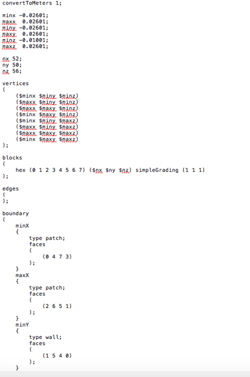
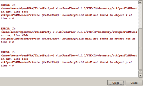
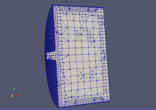
    求助 把snappyHexMesh例题里的modle换了,网格划分都正常checkMesh也正常 为什么在paraview上显示不出来

    OpenFOAM
    2
    9
    4259
    Loading More Posts
    • Oldest to Newest
    • Newest to Oldest
    • Most Votes
    Reply
    • Reply as topic
    Log in to reply
    This topic has been deleted. Only users with topic management privileges can see it.
    • R
      Ryo last edited by

      OpenFoam 新手,现在想用一个有一个孔的模型模拟马赫数=2冲击波,mesh想用snappyHexMesh来做 ,modle的stl file也做好了。 把网上下载的例题里的模型换掉,blockMesh了一下很正常 但是用paraFoam显示的时候按apply就闪退

      0_1498618734192_屏幕快照 2017-06-28 上午11.54.46.png

      按照例题snappyHexMesh后 checkMesh也正常 在paraview上也显示不出来提示也是一样的问题
      0文件夹里的p的25行到39行如下
      0_1498618958170_屏幕快照 2017-06-28 下午12.01.23.png

      X 1 Reply Last reply Reply Quote
      • X
        xpqiu 教授 @Ryo last edited by

        @Ryo 这是虚拟机的问题,在虚拟机里开paraview很不稳定。建议在宿主机下装parview,然后开辟一个虚拟机与宿主机共享的空间,把算例放到共享空间里并在宿主机下开paraview来查看结果。

        R 1 Reply Last reply Reply Quote
        • R
          Ryo @xpqiu last edited by

          @xpqiu 非常感谢这么短时间就回复
          现在已经能在paraview上显示了 但是只显示blockmesh时设定的区域 不现实modle。。 例题的话可以正常显示。
          是不是边界没有设定好。。尝试很久也没有调好
          1_1498635781127_屏幕快照 2017-06-28 下午4.19.52.png 0_1498635781105_屏幕快照 2017-06-28 下午4.19.22.png
          这个是blockmeshdic0_1498635567127_屏幕快照 2017-06-28 下午4.39.06.png

          modle的尺寸是底面半径18mm 长10mm

          在虚拟机上的时候提示这种错误0_1498635629380_屏幕快照 2017-06-28 下午4.18.36.png

          X 1 Reply Last reply Reply Quote
          • X
            xpqiu 教授 @Ryo last edited by

            @Ryo
            可能的原因有:

            1. snappyHexMesh 运行出错了,导致没有生成正常的网格,所以你只能看到blockMesh的网格;
            2. snappyHexMesh 运行的时候,没有加 -overwrite 选项,导致的结果是,snappyHexMesh生成的网格不会覆盖掉blockMesh的网格,而是写在一个新的时刻下面。如果是这种情况,你在paraview里向后调两个时间步就能看到你的model网格了。

            边界条件设置有问题,不会影响到网格的显示。

            R 1 Reply Last reply Reply Quote
            • R
              Ryo @xpqiu last edited by

              @xpqiu 感谢回复!
              是按照例题的步骤来的 加了overwrite。
              应该是snappyHexMeshDic里面编辑出错了,例题里原来的模型有两个inlet,我现在这个只有一个。想问下是怎么指定哪个面是inlet哪个面是outlet的?

              X 1 Reply Last reply Reply Quote
              • X
                xpqiu 教授 @Ryo last edited by

                @Ryo
                inlet 和 outlet 边界条件需要在你的 STL 文件中指定。也就是说,你需要将inlet 和 outlet 面单独导出来。在 STL 文件中,inlet 和 outlet 需要是单独的solid,我给你看一个STL文件的示例:

                solid inlet
                  facet normal 0 1 0
                    outer loop
                       vertex 2.75 7.7 5.52
                       vertex 2.75 7.7 0
                       vertex 0 7.7 0
                    endloop
                  endfacet
                  facet normal 0 1 0
                    outer loop
                       vertex 2.75 7.7 5.52
                       vertex 0 7.7 0
                       vertex 0 7.7 5.52
                    endloop
                  endfacet
                endsolid inlet
                solid outlet
                  facet normal 0 0 -1
                    outer loop
                       vertex 2.75 -0.3 0
                       vertex 2.75 0 0
                       vertex 6.15 -0.3 0
                    endloop
                  endfacet
                  facet normal 0 0 -1
                    outer loop
                       vertex 0 0 0
                       vertex 0 7.7 0
                       vertex 2.75 7.7 0
                    endloop
                  endfacet
                endsolid outelt
                solid other
                  facet normal -1 0 0
                    outer loop
                       vertex 2.75 8 0
                       vertex 2.75 7.7 0
                       vertex 2.75 7.7 5.52
                    endloop
                  endfacet
                  facet normal -1 0 0
                    outer loop
                       vertex 2.75 8 0
                       vertex 2.75 7.7 5.52
                       vertex 2.75 8 6.5
                    endloop
                  endfacet
                  facet normal -1 0 0
                    outer loop
                       vertex 2.75 0 0
                       vertex 2.75 -0.3 0
                       vertex 2.75 0 5.52
                    endloop
                  endfacet
                  facet normal -1 0 0
                    outer loop
                       vertex 2.75 7.7 5.52
                       vertex 2.75 0 5.52
                       vertex 2.75 -0.3 6.5
                    endloop
                  endfacet
                  facet normal -1 -0 0
                    outer loop
                       vertex 2.75 8 6.5
                       vertex 2.75 7.7 5.52
                       vertex 2.75 -0.3 6.5
                    endloop
                  endfacet
                  facet normal -1 -0 0
                    outer loop
                       vertex 2.75 0 5.52
                       vertex 2.75 -0.3 0
                       vertex 2.75 -0.3 6.5
                    endloop
                  endfacet
                endsolid other
                
                R 1 Reply Last reply Reply Quote
                • R
                  Ryo @xpqiu last edited by 李东岳

                  @xpqiu 感谢 回复!真的很感谢
                  学openfoam学的太纠结了。。感觉从建模到网格划分都一团糊 我把我想做的模拟说一下吧希望您能给点指导意见。。

                  想用一个冲击波管发生冲击波然后从一个单一孔喷出,模拟喷出的气体观察在喷出口的气体,并不想模拟在管道内的流动。

                  所以在CAD建模的时候要把气体喷出后的空气区域也放在模型里吗,如果是这样的话inlet是管道的起始位置outlet是空气区域的尾部吗?

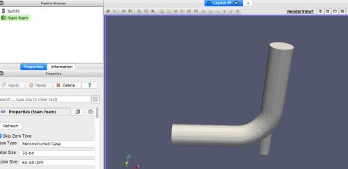
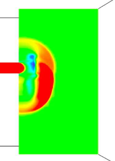
                  这个是前辈用fluent做出来的葱两个孔喷出的
                  0_1498790541570_屏幕快照 2017-06-30 上午11.33.21.png 0_1498790544659_屏幕快照 2017-06-30 上午11.32.47.png

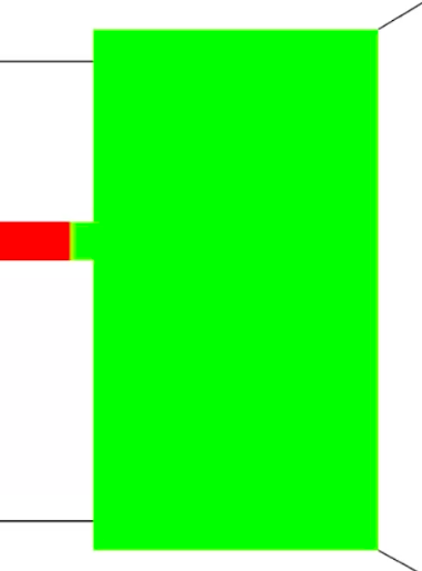
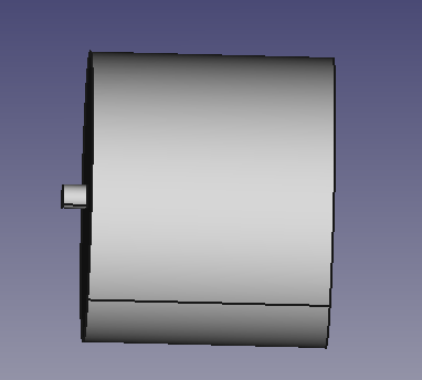
                  现在做了一个有3mm长的管道和一个18mm半径20mm长的圆柱,圆柱用来表示从管道喷出的空气区域。

                  0_1498791182722_屏幕快照 2017-06-30 上午11.47.05.png

                  1 Reply Last reply Reply Quote
                  • X
                    xpqiu 教授 last edited by

                    对,后的空气区域也要用CAD画出来,而且应该画得足够大以减少边界条件的影响。画网格的时候,空气区域中心部分与喷口相接的位置要画得很密,外围可以逐渐变稀。inlet 是管道起始位置,outlet可以是空气区域尾部,但是注意空气区域的圆柱面也可以用出口边界,因为那个圆柱面不是一个实体的壁面,所以不能用无滑移壁面边界条件。圆柱面具体是用出口边界更好还是slip边界更好,这个我没有经验,可能要试试才知道。但如果你的空气区域足够大,应该影响不大。

                    你说不需要模拟在管道内的流动,那还有一种选择是直接忽略管道部分,而用管道部分的尾部当作喷口。但是这样做的代价是你可能需要自己写一个边界条件,来模拟喷口的冲击波。

                    R 1 Reply Last reply Reply Quote
                    • R
                      Ryo @xpqiu last edited by

                      @xpqiu 感谢回复!
                      现在把inlet,outlet和本体分开转换成stl文件 然后snappyHexMesh了一下
                      0_1499148821716_屏幕快照 2017-07-04 下午3.07.55.png

                      圆柱是r=18mm h=20mm inlet尺寸是r=1.5mm,h=3mm这样够不够大?现在想按您说的把空气区域和喷口区域网格如何变的密集?该添加哪些代码。。 求指导一下
                      这个是我现在的snappyHexMeshDic

                      FoamFile
                      {
                      version 2.0;
                      format ascii;
                      class dictionary;
                      object snappyHexMeshDict;
                      }

                      castellatedMesh true; // make basic mesh ?
                      snap true; // decide to snap back to surface ?
                      addLayers true; // decide to add viscous layers ?

                      geometry // Load in STL files here
                      {
                      inlet.stl {type triSurfaceMesh; name inlet;}
                      outlet.stl {type triSurfaceMesh; name outlet;}
                      wall.stl {type triSurfaceMesh; name wall;}
                      volume.stl {type triSurfaceMesh; name volume;}
                      refinementBox {type searchableBox; min (-0.03 -0.03 -0.03); max ( 0.03 0.3 0.3);}
                      };

                      castellatedMeshControls
                      {
                      maxLocalCells 1000000; //max cells per CPU core
                      maxGlobalCells 2000000; //max cells to use before mesh deletion step
                      minRefinementCells 10; //was 0 - zero means no bad cells are allowed during refinement stages
                      maxLoadUnbalance 0.10;
                      nCellsBetweenLevels 1; // expansion factor between each high & low refinement zone

                      // Explicit feature edge refinement
                      // ~~~~~~~~~~~~~~~~~~~~~~~~~~~~~~~~
                      
                      features // taken from STL from each .eMesh file created by "SurfaceFeatureExtract" command
                      (
                          {file "inlet.eMesh"; level 2;} 
                          {file "outlet.eMesh"; level 2;} 
                          {file "wall.eMesh"; level 2;} 
                      );
                      
                      // Surface based refinement
                      // ~~~~~~~~~~~~~~~~~~~~~~~~
                      
                      refinementSurfaces // Surface-wise min and max refinement level
                      {
                      inlet {level (0 0);}
                      

                      outlet {level (0 0);}
                      wall {level (3 3);}
                      }

                      resolveFeatureAngle 80;  // Resolve sharp angles // Default 30
                      refinementRegions        // In descending levels of fine-ness
                      {volume {mode distance; levels ((0.0006 3) (0.002 2) (0.01 1));}} // was ((0.001 4) (0.003 3) (0.01 2))
                      locationInMesh (0.01 0 0);  //to decide which side of mesh to keep **
                      allowFreeStandingZoneFaces true;
                      

                      }

                      // Settings for the snapping.
                      snapControls
                      {
                      nSmoothPatch 3;
                      tolerance 4.0;
                      nSolveIter 30;
                      nRelaxIter 5;
                      nFeatureSnapIter 15; // default is 10

                      // New settings from openfoam 2.2 onwards for SHMesh

                      implicitFeatureSnap false; // default is false - detects without doing surfaceFeatureExtract
                      explicitFeatureSnap true; // default is true
                      multiRegionFeatureSnap false; // deafault is false - detects features between multiple surfaces

                      }

                      // Settings for the layer addition.
                      addLayersControls //add the PATCH names from inside the STL file so STLpatchName_insideSTLName
                      {
                      relativeSizes false; // was true
                      layers
                      {
                      wall
                      {nSurfaceLayers 3;} // was 3
                      }

                      expansionRatio 1.3;
                      finalLayerThickness 0.00016; //was 0.00016
                      minThickness 0.00008; //was 0.00008
                      nGrow 0; // was 1 
                      
                      
                      // Advanced settings
                      
                      featureAngle 80; // was 70 //- When not to extrude surface. 0 is flat, 90 is right angle.
                      nRelaxIter 3;  //- Max# of snapping relaxation iter. Should stop before upon reaching a correct mesh.
                      nSmoothSurfaceNormals 1;  // Number of smoothing iterations of surface normals
                      nSmoothNormals 3; // Number of smoothing iterations of interior mesh movement direction
                      nSmoothThickness 10;  // Smooth layer thickness over surface patches
                      maxFaceThicknessRatio 0.5; // Stop layer growth on highly warped cells
                      maxThicknessToMedialRatio 0.3; // Reduce layer growth where ratio thickness to medial distance is large
                      minMedianAxisAngle 130;  // Angle used to pick up medial axis points
                      nBufferCellsNoExtrude 0;   // Create buffer region for new layer terminations
                      nLayerIter 50; // Overall max number of layer addition iterations
                      

                      }

                      // Generic mesh quality settings. At any undoable phase these determine
                      // where to undo.
                      meshQualityControls
                      {
                      maxNonOrtho 65;
                      maxBoundarySkewness 20;
                      maxInternalSkewness 4;
                      maxConcave 80;
                      minFlatness 0.5;
                      minVol 1e-13;
                      minTetQuality 1e-9;
                      minArea -1;
                      minTwist 0.02;
                      minDeterminant 0.001;
                      minFaceWeight 0.02;
                      minVolRatio 0.01;
                      minTriangleTwist -1;

                      // Advanced
                      
                      nSmoothScale 4;
                      errorReduction 0.75;
                      

                      }

                      // Advanced

                      debug 0;

                      // Merge tolerance. Is fraction of overall bounding box of initial mesh.
                      // Note: the write tolerance needs to be higher than this.
                      mergeTolerance 1E-6;

                      // ************************************************************************* //

                      1 Reply Last reply Reply Quote
                      • First post
                        Last post

                      CFD中文网 | 东岳流体 | 京ICP备15017992号-2
                      论坛登录问题反馈可联系 li.dy@dyfluid.com